How To Write A Realtime Raytracer In About 200 LOC
How To Write A Realtime Raytracer In About 200 LOC
Implementing a raytracer is nothing hard, especially shitty ones.
On a high level perspective, raytracer is just:
- Cast ray from you to every
pixelon the camera view - For each ray, iter through all triangles and find the nearest hit, if there is one. If hit:
- interpolate the values of the triangle
- accumulate the colors
- and repeat til miss or
max_bounce - Set the accumulated color.
Very simple, right?
I'll be using wgsl for shaders. I implemented this raytracer for my class, so I cannot publicly disclose all of the code. In this post, let's just forget about those boilerplate rust codes and just focus on the real shader part. If you are smart enough to find this post, you'll figure those boilerplate code out.
Warning
This implementation uses a naive O(N) loop, checking every triangle for every ray. It works great for simple scenes (like a Cornell Box with a few cubes), but it will melt your GPU if you load a complex mesh. In a production raytracer, you would use an acceleration structure like BVH (Bounding Volume Hierarchy) to turn this O(N) search into O(logN). But that takes way more than 200 lines!
And here is one of the example output:
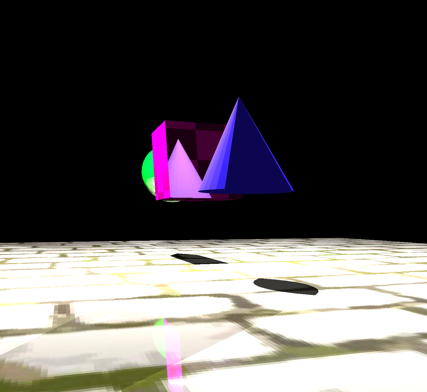
So let's start.
Preface?
Here are some things that we might need to have a consensus on. Since we are doing raytracing, we need to cast rays (apparently). The way I prefer is to create a StorageTexture (basically texture for direct access for reading, writing and compute shaders) as the same size of our output to render to. And since we have to do a compute pass to do tracing (because we want the gpu program to run arbitrarily so I can specify my rays, not as the default render programs which vertex shaders will be called upon each vertices), we need a separate pass for rendering the generated texture to screen, so we need two shaders.
I will not be specific on the bindgroup and binding thingy here, because apparently you can customize them as you want.
I will not put the code together because it might violate campus rules.
This is a very shitty and naive raytracer.
Cast Rays From Camera
To cast rays for each pixel in the camera_view, apparently, we need the pixels and the camera. So let's say we have:
struct Camera {
    eye: vec3<f32>,
    _pad0: f32,
    up: vec3<f32>,
    _pad1: f32,
    right: vec3<f32>,
    _pad2: f32,
    forward: vec3<f32>,
    _pad3: f32,
    aspect: f32,
    fovy: f32,
};

var<uniform> camera: Camera;
var output_texture: texture_storage_2d<rgba32float, write>;
So here, our camera struct is basically defining a coordinate system, with fovy (y field of view) and aspect ratio, which then we can just calculate fovx whenever we need. The output_texture is just the texture that we'll be writing to. On the cpu side, we'll be splitting tasks into cubes but we are 2d rendering here so our third param for @workgroup_size will be 1.
WebGPUis very specific about paddings, at leastwgpuin rust is. I do think the paddings are needed here in the shader and are definitely needed on thecpuside.
@compute @workgroup_size(8, 8, 1)
fn main(@builtin(global_invocation_id) global_id: vec3<u32>) {
    let pixel = global_id.xy;
    let resolution = textureDimensions(output_texture);

    // Bounds check
    if pixel.x >= resolution.x || pixel.y >= resolution.y {
        return;
    }

    // Generate ray for this pixel
    let uv = (vec2<f32>(pixel) + 0.5) / vec2<f32>(resolution);
    let ndc = vec2<f32>(uv.x * 2.0 - 1.0, -(uv.y * 2.0 - 1.0)); // Flip Y to fix upside-down camera

    let aspect = camera.aspect;
    let fov_scale = tan(camera.fovy * 0.5 * PI / 180.0);

    let ray_dir = normalize(
        camera.right * ndc.x * aspect * fov_scale + camera.up * ndc.y * fov_scale + camera.forward
    );

    var color = trace(camera.eye, ray_dir);

    textureStore(output_texture, vec2<i32>(pixel), color);
}
This will be the resulting code, nothing complex, just mapping the pixel coordinate to uv coordinate and then to directions using the camera direction vectors.
Notice that in the above code, we need to negate the y value when we are converting from uv coordinate to ndc coordinate because in our usual life, like Minecraft, y is pointing upward, while in uv, it starts from top left, so its y coordinate is pointing downwards, which will make your entire thing upside down if you don't negate the y value.
Trace The Rays
Here is the setup code:
// vo_p: the source of our ray
// vr_d: the direction of our ray
// tidx: the index of our triangle we are targeting
fn ray(vo_p: vec3<f32>, vr_d: vec3<f32>, tidx: u32) -> HitRecord {
    // type just to store some useful information on this record
    var out: HitRecord;
    // Let's say these are the vertices of the triangle we are targeting
    let v0_p = vertices[indices[tidx * 3u + 0u]].position;
    let v1_p = vertices[indices[tidx * 3u + 1u]].position;
    let v2_p = vertices[indices[tidx * 3u + 2u]].position;
    ...
}
Trace the ray is fairly simple, each ray is just a direction with a source, and all we need to figure out is whether we hit a triangle or not. Simple geometry, two vertices(points) determine a line, and three vertices determine a plane. So what do here is to find where does the ray intersect the plane, and then whether the point on the plane is inside the triangle.
Lets start with detecting the hit point on the plane each triangle lies in.
Intuitively, we are just trying to find a point on the direction of our ray, that some vectors sourced from this point that lays on the plane of the triangle we are targeting is perpendicular to the triangle's normal vector.
In my example, I'll use v0_p as the reference point (just some random point on the plane that I'll use for almost all operations, doesn't really matter which point you choose on the plane) on the triangle and the plane.
In math, it looks like this is the unknown we are trying to solve:
Lets reduce this math equation:
Since dot(a, b) is commutative, and we want to isolate d, we got:
This math then translated into this code:
fn ray(vo_p: vec3<f32>, vr_d: vec3<f32>, tidx: u32) -> HitRecord {
    ...
    let plane_normal_d = normalize(cross(v1_p - v0_p, v2_p - v0_p));
    let denom = dot(plane_normal_d, vr_d);
    if abs(denom) < epsilon {
        out.hit = false;
        return out;
    }
    let hit_v = -dot(plane_normal_d, vo_p - v0_p) / denom;
    if hit_v < epsilon {
        out.hit = false;
        return out;
    }
    let hit_p = vo_p + vr_d * hit_v;
    ...
}
There are two early exit branches above, the first one happens when our ray is parallel to the triangle, and the second happens when our ray sourced from the triangle.
Now that we've got the hit point on the plane, the last step is to figure out if that point actually sits inside the triangle.
To do this, we check the rotation direction between each triangle edge and the vector from that edge’s vertex to our hit point. If all those rotations spin the same way, the point's inside. If one of them flips, it's outside.
We keep the edge directions in the triangle's winding order (v0 -> v1 -> v2 -> v0) and measure each cross(edge, p - vertex). If all three crosses have the same sign when dotted with the plane normal, the rotations are consistent and the point is inside. Flipping any vector would flip a sign and break the test.
We can carefully design our winding direction so that if the point is inside the triangle, its the same direction as the triangle's surface normal
And here is the code:
fn ray(vo_p: vec3<f32>, vr_d: vec3<f32>, tidx: u32) -> HitRecord {
    ...
    // Each edge follows the same vertex order (v0 -> v1 -> v2 -> v0)
    let edge0_s = v1_p - v0_p;
    let edge1_s = v2_p - v1_p;
    let edge2_s = v0_p - v2_p;

    let cross0_d = cross(edge0_s, hit_p - v0_p);
    let cross1_d = cross(edge1_s, hit_p - v1_p);
    let cross2_d = cross(edge2_s, hit_p - v2_p);

    let same0 = dot(cross0_d, plane_normal_d) > 0.0;
    let same1 = dot(cross1_d, plane_normal_d) > 0.0;
    let same2 = dot(cross2_d, plane_normal_d) > 0.0;
    ...
}
Remember how we did our rotation for plane normal: cross(v1_p - v0_p, v2_p - v0_p). In this case all normals we got if the point is within the triangle are in the same direction as this normal. And now we just need to construct our HitRecord and return it:
fn ray(vo_p: vec3<f32>, vr_d: vec3<f32>, tidx: u32) -> HitRecord {
    ...
    out.hit = same0 && same1 && same2;
    out.t = hit_v;
    out.idx = tidx;

    return out;
}
Interpolate Triangles
The triangle interpolation methods I used here is barycentric interpolation, you can read more about it here. The idea is for a point p inside a triangle, the weight of a vertex v is calculated the ratio of the area of the triangle formed by p and the edge opposed tov to the area of the entire triangle. We calculate the weight for all three vertices of the triangle once hit.
fn interpolate(vo_p: vec3<f32>, vr_d: vec3<f32>, hit: HitRecord) -> Vertex {
    var out: Vertex;
    let tidx = hit.idx;
    out.position = vo_p + vr_d * hit.t;

    let v0 = vertices[indices[tidx * 3u + 0u]];
    let v1 = vertices[indices[tidx * 3u + 1u]];
    let v2 = vertices[indices[tidx * 3u + 2u]];
    let v0_p = vertices[indices[tidx * 3u + 0u]].position;
    let v1_p = vertices[indices[tidx * 3u + 1u]].position;
    let v2_p = vertices[indices[tidx * 3u + 2u]].position;

    let triangle_area = length(cross(v1_p - v0_p, v2_p - v0_p)) / 2.0;
    let area0 = length(cross(v1_p - out.position, v2_p - out.position)) / 2.0;
    let area1 = length(cross(v2_p - out.position, v0_p - out.position)) / 2.0;
    let area2 = length(cross(v0_p - out.position, v1_p - out.position)) / 2.0;

    out.uv = (v0.uv * area0 + v1.uv * area1 + v2.uv * area2) / triangle_area;
    out.normal = normalize(v0.normal * area0 + v1.normal * area1 + v2.normal * area2);

    return out;
}
Here I am only interpolating uv coordinates and normal vectors. Feel free to add more if needed.
Face Culling
To do simple face culling, we can just not sample a triangle and go on to the next iteration if we are "inside" a object, in other words, when you got a positive value from dot vertex.normal with ray. A positive value indicates both vectors are in the same direction, and normal of a triangle should shoot from the triangle to "outside".
I simply have this in my tracing function.
if dot(vertex.normal, ray) > 0.0 {
    continue;
}
Light Sources
For each triangle we hit, we need to see how much light the triangle perceive from each light source, then we can determine the color our ray will sample. To do that, we need to loop through every light source, determine if any other triangle blocks it. Since here we are not dealing with transparency, we can simplify the logic.
This in_shadow function utilize the ray function we have above to see if any triangle is in between the light source and the targeted triangle:
fn in_shadow(vertex: Vertex, light_pos: vec3<f32>) -> bool {
    let origin = vertex.position + vertex.normal * epsilon;
    let light_dir = normalize(light_pos - origin);
    let light_dist = length(light_pos - origin);
    let num_triangles = input_bounds.index_count / 3u;

    for (var i = 0u; i < num_triangles; i++) {
        let shadow_hit = ray(origin, light_dir, i);
        if shadow_hit.hit && shadow_hit.t < light_dist && shadow_hit.t > epsilon {
            return true;  // Early exit - already in shadow
        }
    }
    return false;
}
And for the light function, we just loop through all light sources and see if any of them is not in shadow, we then calculate the light contribution through distance attenuation and lambertian diffuse, and then we add each light sample to produce the final output of this function.
fn light(vertex: Vertex, material: u32) -> vec4<f32> {
    let albedo = ... // get albedo color through material id

    var out: vec4<f32> = vec4<f32>(0.0, 0.0, 0.0, 1.0);
    // you can also do this if you have an ambient light
    // var out: vec4<f32> = vec4<f32>(ambient_light.color * albedo, 1.0);

    for (var lidx = 0u; lidx < input_bounds.light_count; lidx++) {
        let light = point_lights[lidx];

        if !in_shadow(vertex, light.position) {
            let light_dir = normalize(light.position - vertex.position);
            let distance = length(light.position - vertex.position);

            // Distance attenuation (inverse square law)
            let attenuation = 1.0 / (distance * distance);

            // Lambertian diffuse
            let n_dot_l = max(dot(vertex.normal, light_dir), 0.0);

            // Simple diffuse contribution
            let diffuse = albedo * n_dot_l * light.intensity * attenuation;

            out += vec4<f32>(diffuse, 0.0);
        }
    }

    return out;
}
Reflection
While classic CPU ray tracers often use recursion (functions calling themselves), GPU-based path tracers prefer an iterative approach to avoid stack overflow.
We use a variable called throughput. It starts at 1.0 (white) and gets multiplied by the material color at each bounce. This tracks the 'history' of the light ray - essentially remembering how much energy has been absorbed by surfaces along the path.
In a proper PBR engine, roughness determines the micro-facet distribution (blurriness). Here, for the sake of simplicity, we use it as an attenuation factor to simulate the energy loss of scattered rays without doing expensive Monte Carlo sampling.
Note
In production, the throughput calculation involves complex BRDF and PDF math, and roughness affects how sharp light will reflect instead.
Calculation is fairly simple:
fn trace(vo: vec3<f32>, vr: vec3<f32>) -> vec4<f32> {
    ...
    for (var iter = 0u; iter < system_bounds.max_depth; iter ++) {
        ...
        // Direct lighting (diffuse component)
        let diffuse_strength = 1.0 - mat.metallic;
        if diffuse_strength > epsilon {
            let lit = light(vertex, tri_material_ids[closest_hit.idx]);
            out += vec4<f32>(lit.rgb * throughput * diffuse_strength, 0.0);
        }

        // Only do reflections for metallic surfaces
        // Diffuse surfaces stop bouncing after direct lighting
        if mat.metallic < epsilon {
            break;  // Stop bouncing for non-metallic surfaces
        }

        // Reflection/Bounce for metals
        let reflection_color = mat_albedo;
        throughput *= reflection_color;

        // Roughness affects reflection direction
        // For now, just use perfect reflection (roughness would require random sampling)
        origin = vertex.position + vertex.normal * epsilon;
        ray = reflect(ray, vertex.normal);

        // Attenuate by roughness
        throughput *= (1.0 - mat.roughness * 0.5);
    }
    ...
}
Assemble The `trace` Function
The functionality of trace in my code is to trace a ray and give a vec4 color result.
fn trace(origin: vec3<f32>, ray: vec3<f32>) -> vec4<f32> {
    var closest_hit: HitRecord;
    var out: vec4<f32> = vec4<f32>(0.0);
    var throughput = vec3<f32>(1.0);

    let num_triangles = input_bounds.index_count / 3u;

    for (var iter = 0u; iter < system_bounds.max_depth; iter ++) {

        closest_hit.hit = false;
        closest_hit.t = 999999.0;
        // Test against ALL triangles
        for (var i = 0u; i < num_triangles; i++) {
            let hit = ray(origin, ray, i);
            if hit.hit && hit.t < closest_hit.t {
                closest_hit = hit;
            }
        }

        if !closest_hit.hit {
            // Ray missed all geometry - sample sky sphere
            // You can sample a skybox instead
            // let sky_color = sample_sky(ray);
            let sky_color = vec4<f32>(0.1, 0.1, 0.1, 1.0);
            return out + vec4<f32>(sky_color * throughput, 1.0);
        }

        let vertex = interpolate(origin, ray, closest_hit);

        // if it is inside
        if dot(vertex.normal, ray) > 0.0 {
            continue;
        }

        let mat = materials[tri_material_ids[closest_hit.idx]];

        // Sample texture if available for this material
        // You can instead store an index of a texture for a material
        // and use the index and the interpolated uv to sample the texture
        var mat_albedo = mat.albedo;

        // Code from previous section
    }

    return out;
}
Sample The Result
Since everything above we did is create a screen sized texture that contains the raytraced result, we haven't sampled the texture and put it on the screen. To do this, we need to create a full screen triangle and just sample the texture storage. You might wonder why we use coordinates like ? This defines a single generic triangle that is larger than the screen. It covers the entire [-1, 1] NDC range (the screen) without needing two triangles (a quad). This avoids the diagonal edge processing in the middle of the screen, which is a classic optimization trick.
@group(0) @binding(0) var raytraced_texture: texture_2d<f32>;

@vertex
fn vs_main(@builtin(vertex_index) vid: u32) -> @builtin(position) vec4<f32> {
    var pos = array<vec2<f32>, 3>(
        vec2<f32>(-1.0, -1.0),
        vec2<f32>(3.0, -1.0), // 3.0 here
        vec2<f32>(-1.0, 3.0)  // and here
    );
    return vec4<f32>(pos[vid], 0.0, 1.0);
}

@fragment
fn fs_main(@builtin(position) input: vec4<f32>) -> @location(0) vec4<f32> {
    // input.xy is already in pixel coordinates, just load directly
    let pixel = vec2<i32>(input.xy);
    return textureLoad(raytraced_texture, pixel, 0);
}
Conclusion
My code, with some extra workarounds because of historic reasons, ends up to be around LOC. As I enhance my knowledge in computer graphics, I will be posting performance update to my raytracer and follow up blog posts.
$ tokei ./tracing.wgsl
━━━━━━━━━━━━━━━━━━━━━━━━━━━━━━━━━━━━━━━━━━━━━━━━━━━━━━━━━━━━━━━━━━━━━━━━━━━━━━━━━
 Language              Files        Lines         Code     Comments       Blanks
━━━━━━━━━━━━━━━━━━━━━━━━━━━━━━━━━━━━━━━━━━━━━━━━━━━━━━━━━━━━━━━━━━━━━━━━━━━━━━━━━
 WebGPU Shader Lan|        1          381          254           55           72
━━━━━━━━━━━━━━━━━━━━━━━━━━━━━━━━━━━━━━━━━━━━━━━━━━━━━━━━━━━━━━━━━━━━━━━━━━━━━━━━━
 Total                     1          381          254           55           72
━━━━━━━━━━━━━━━━━━━━━━━━━━━━━━━━━━━━━━━━━━━━━━━━━━━━━━━━━━━━━━━━━━━━━━━━━━━━━━━━━
Comments